Warning
Important Notice: The DynaArm is currently a prototype and not ready for commercial use. It is intended solely for research and development purposes. Users are responsible for ensuring safe operation during its use.
Integration and Safety
This section provides guidelines for integrating the DynaArm into your setup and ensuring safe operation. Proper integration and adherence to safety measures are critical for optimal performance and to minimize risks.
Base Plate Mounting Instructions
Choose a Stable Base:
Select a surface that can securely support the weight of the robot (9 kg) and any additional payload.
The base should be level and free of vibrations.
Secure the Robot:
Follow the dimensions provided in the technical drawing below for proper alignment.
The following drawing indicates the base plate’s mounting features for secure attachment of the DynaArm.
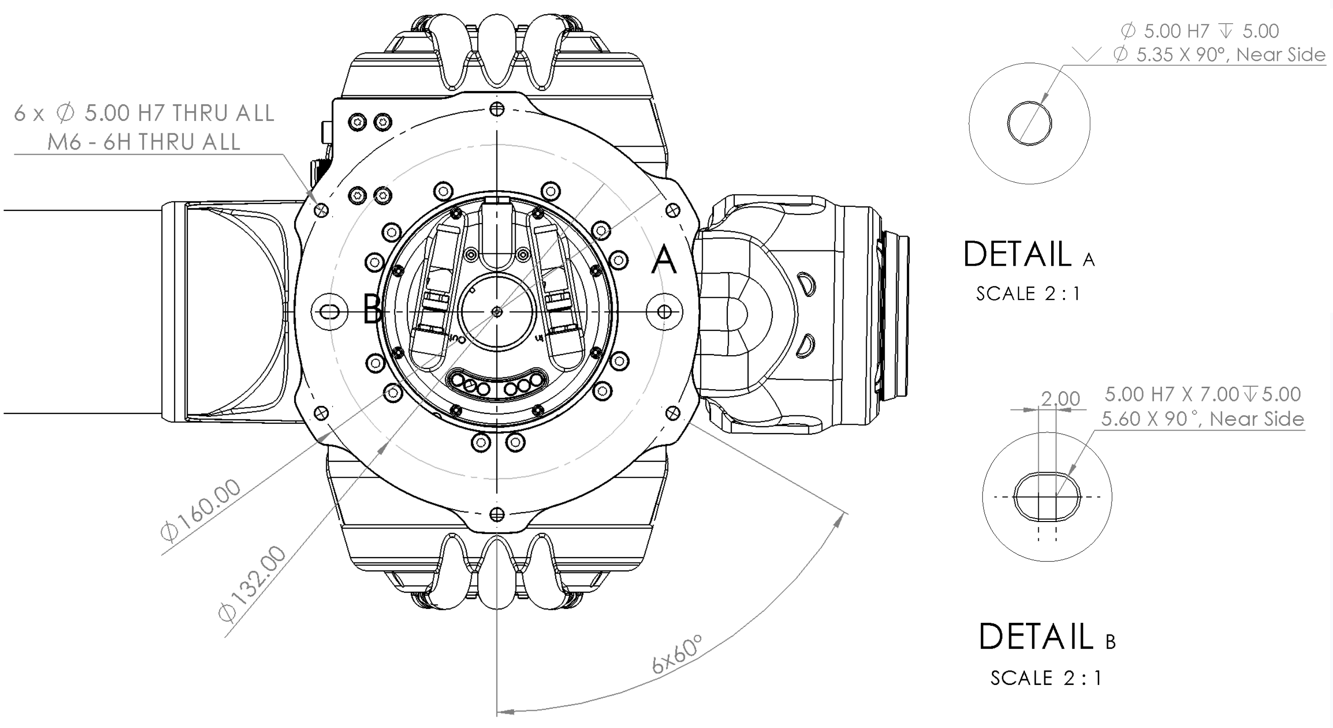
Fig. 1 Drawing showing the mounting features of the DynaArm base plate
Detail |
Description |
|---|---|
A |
Alignment hole |
B |
Alignment slot |
Mount the robot in either a bottom or top configuration, depending on the application, as shown in the following drawings.
The following drawing illustrates the steps required for the bottom mounting of the robot arm.
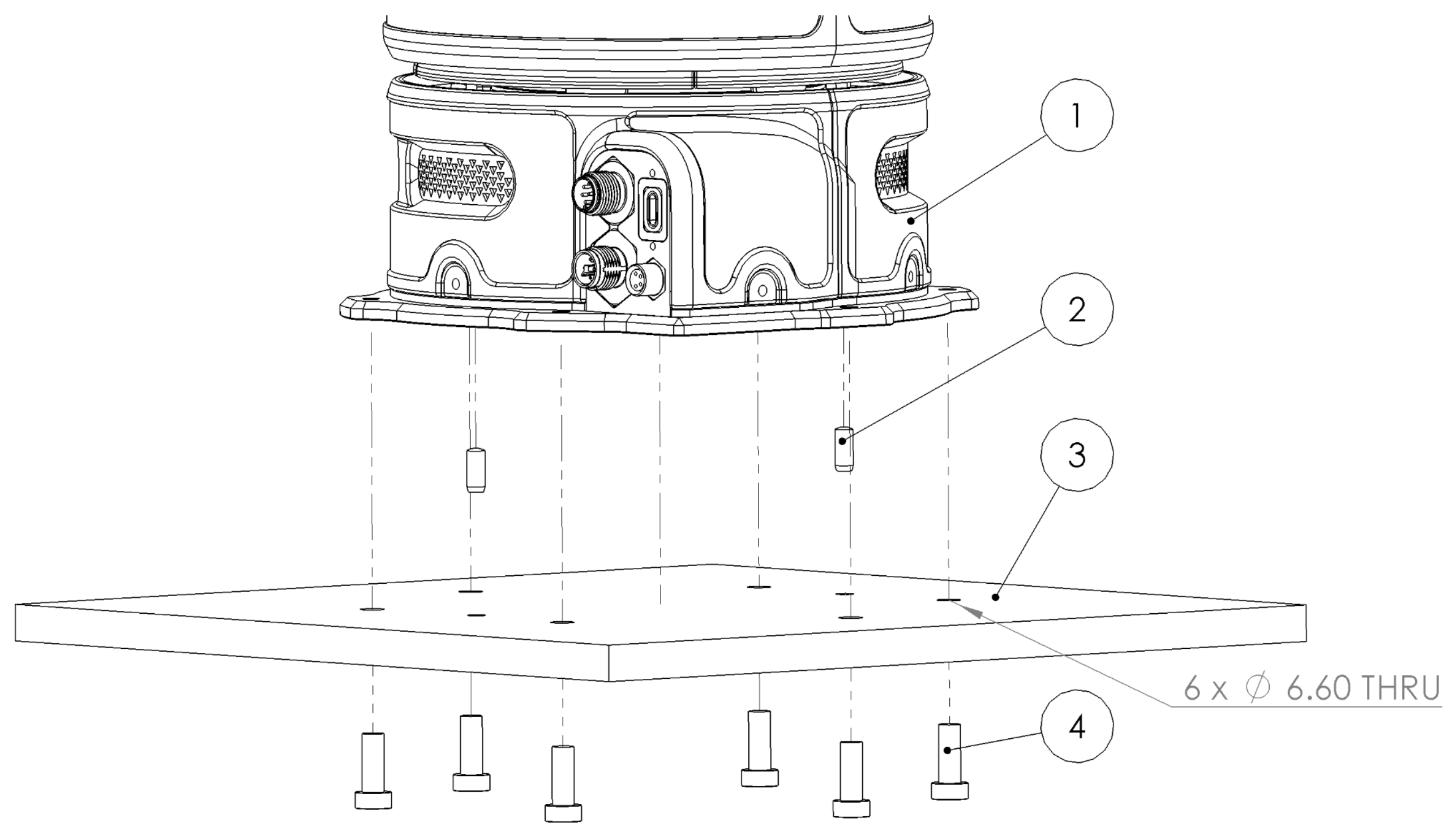
Fig. 2 Illustration of the bottom mounting configuration of the DynaArm
Item |
Description |
Details |
|---|---|---|
1 |
DynaArm |
|
2 |
2x Dowel Pins Ø5 H7 |
Secure the robot arm’s position and prevent further movement. |
3 |
Ground |
Ensure clearance for M6 screws at the positions marked on the diagram Fig. 1. |
4 |
6x M6 metric screws, Strength class 8.8 |
Tighten the screws with a recommended torque of 9.5 Nm. |
The following drawing illustrates the steps required for the top mounting of the robot arm.
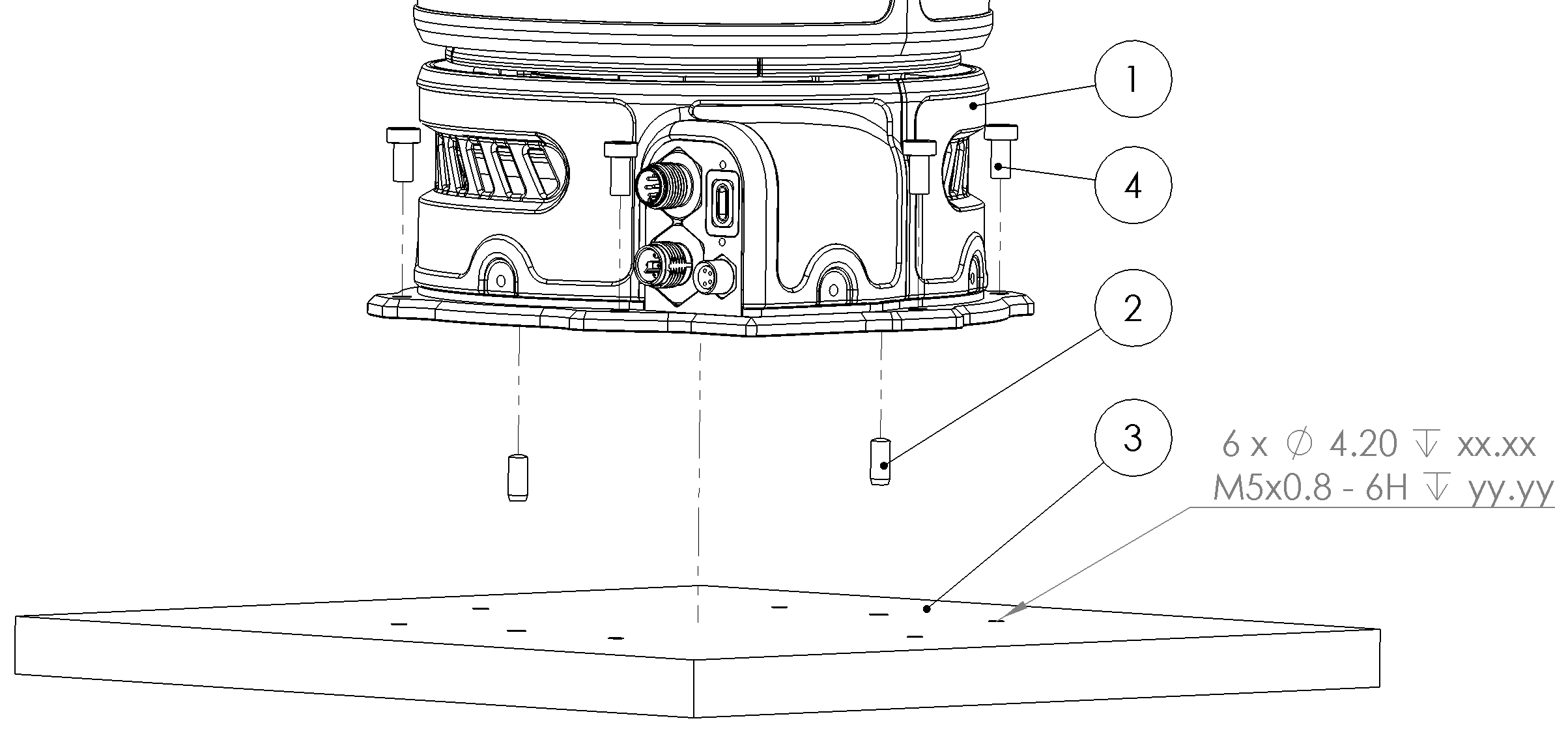
Fig. 3 Illustration of the top mounting configuration of the DynaArm
Verify Stability:
Ensure the robot does not wobble or shift during operation.
Tighten all screws and bolts securely.
End Effector Mounting Instructions
The DynaArm flange provides the following holes for mounting a payload, end effector, or adapter plate. The drawing below shows the alignment holes, tightening holes, and general purpose/cable management mounting threads available on the flange.
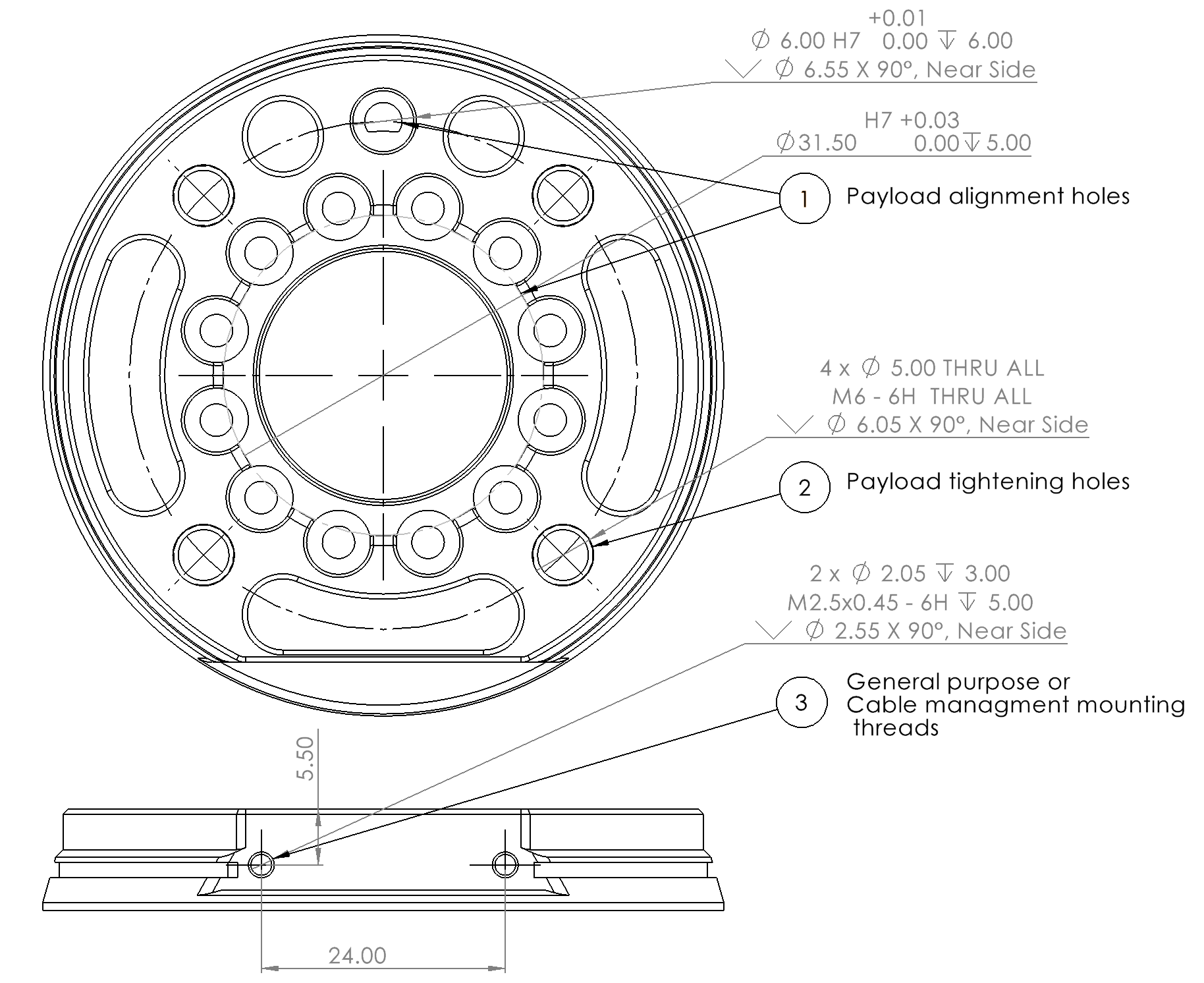
Fig. 4 Drawing showing the flange alignment and mounting holes on the DynaArm end effector interface
Item |
Description |
Details |
|---|---|---|
1 |
Payload alignment holes |
Ø 6.00 H7 and Ø 31.50 H7 |
2 |
Payload tightening holes |
4 × Ø 5.00 THRU ALL / M6 - 6H THRU ALL; countersunk Ø 6.05 × 90°, near side |
3 |
General purpose or cable management mounting threads |
M2.5 |
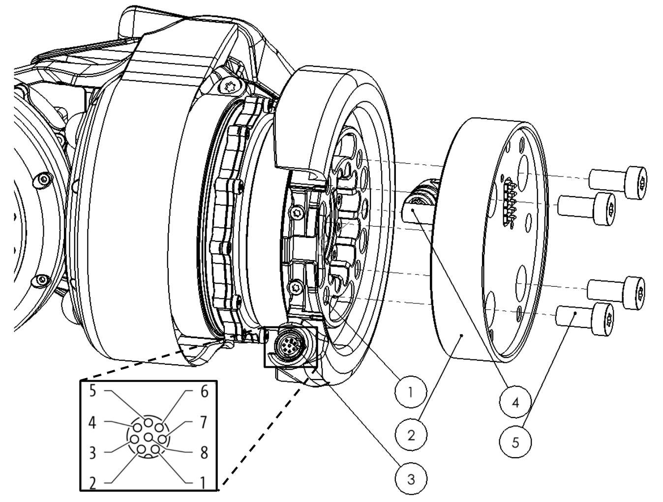
Fig. 5 Illustration of the end effector mounting procedure on the DynaArm
Item |
Description |
Details |
|---|---|---|
1 |
DynaArm flange |
ISO 9409-1-50-4-M6 |
2 |
End effector or adapter plate |
ISO 50-4-M6 |
3 |
General purpose connector (end effector side) |
M8 8 Pin circular connector female |
4 |
Alignment dowel pin Ø6 H7 |
Lenghth depends (e.g., Ø6x14mm) |
5 |
M6 metric screws, Strength class 8.8 |
Tighten torque of 9.5 Nm. Length depends (e.g., M6x12mm) |
The following drawing illustrates the steps required for the end effector mounting on the robot arm.
Wiring and Connections
Proper wiring and connections are essential for safe and reliable operation of the DynaArm. The following interfaces are available:
Power Connector: Mandatory for operation. Use a power supply according to the recommendation.
EtherCAT Connector: Required for communication with the controller.
USB Type-C Connector: For peripherals with USB interface.
General Purpose Connector: For optional peripherals as grippers and more. (Male on the arm side, Female on the end effectorside )
Ensure all mandatory connections are made before powering on the system. Optional interfaces can be used as needed for your application.
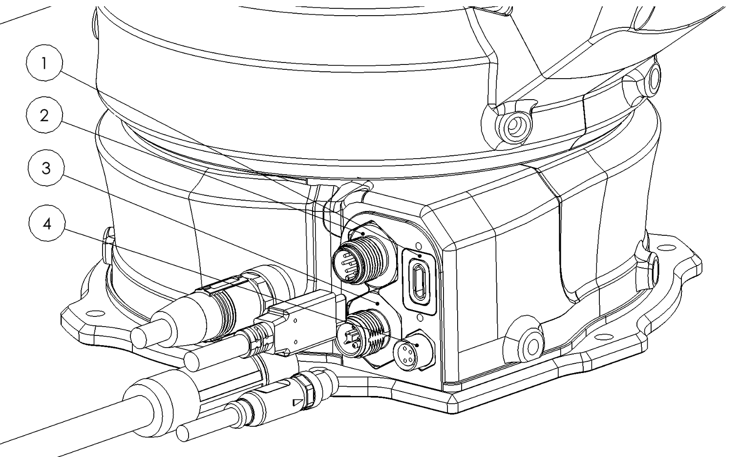
Item |
Description |
Details |
|---|---|---|
1 |
USB Type C connector |
Capable of USB 3.2 Gen 2x2 (20 Gbit/s) |
2 |
General purpose connector |
M8 depending on the arm version, A coded. General pupose connector for additional peripherals. |
3 |
Power connector |
M12, T Coded or A Coded depending on the arm version |
4 |
EtherCAT connector |
M8 A coded |
Connectors pinout
The Pinout of the circular connectors are provided:
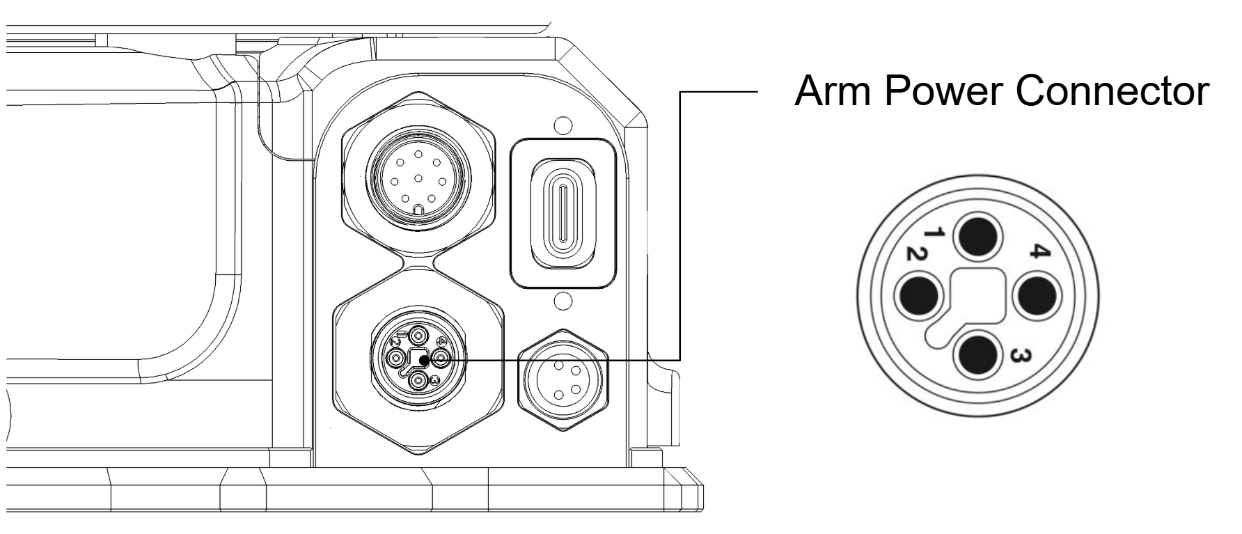
Fig. 6 Illustration of the arm power connector pinout
Pin |
Polarity |
Color |
|---|---|---|
1 |
- |
Brown |
2 |
+ |
White |
3 |
+ |
Blue |
4 |
- |
Black |
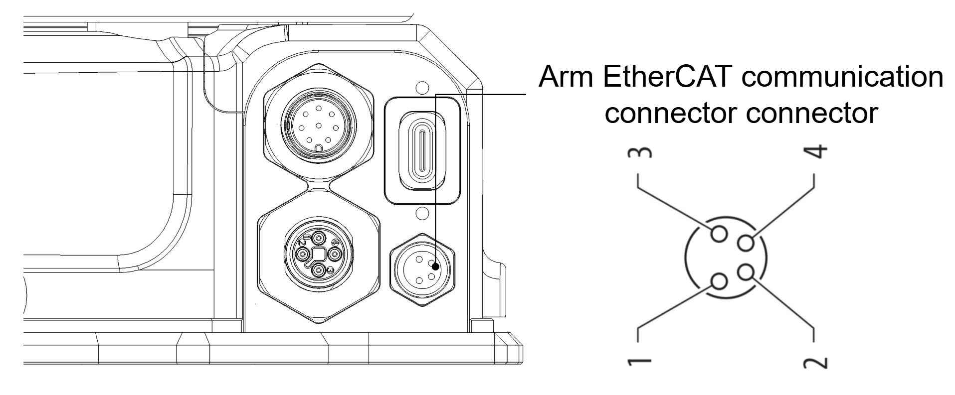
Fig. 7 Illustration of the EtherCAT connector pinout
Pin |
Polarity |
Color |
|---|---|---|
1 |
TX_P |
Brown |
2 |
RX_N |
White |
3 |
RX_P |
Blue |
4 |
TX_N |
Black |
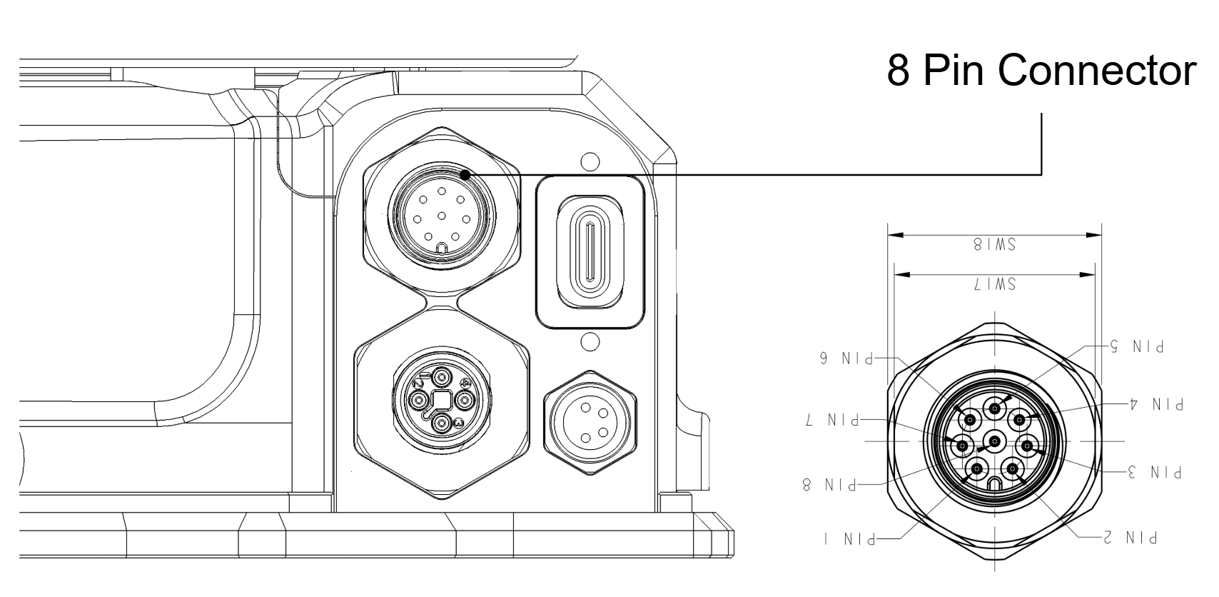
Fig. 8 Illustration of the general purpose connector pinout
Connection procedure
Power Connection:
Use a 48 V power supply that meets the specifications listed in the Technical Specifications section.
EtherCAT Connection:
Connect the EtherCAT cable to the robot and the Controller PC.
First, identify which network interface will be used for EtherCAT communication:
# List all network interfaces
ip link

# Show detailed information about network interfaces
ip addr

# Alternative method to list network interfaces
ls /sys/class/net/
Look for an interface that is typically named
eth0,eth1,enp0s3, or similar. EtherCAT devices usually appear as standard Ethernet interfaces.
Cable Management:
Route cables away from moving parts to avoid entanglement.
Use cable ties or channels to secure cables.
Power Supply Requirements
The DynaArm is designed to operate on a 48V DC power source, making it well-suited for battery-powered and mobile applications. For benchtop development, demonstrations, and stationary use, a stable DC power supply is required.
Recommended Power Supply Specifications
For most applications, a 48V DC power supply with a 20A current rating will be sufficient. To handle regenerative braking and absorb voltage spikes, we recommend connecting a 10mF capacitor across the power supply’s output terminals.
For less demanding tasks, such as those primarily involving gravity compensation with minimal or low-speed movements, a power supply with a lower current rating may be adequate. The power consumption is directly related to the mechanical power exerted by the end-effector, which is a function of payload and movement speed.
When selecting a power supply, it is crucial to choose a model with the following features:
Current Limiting: The power supply should “cap” its output current at the maximum rating rather than shutting down when the arm attempts to draw excess current.
Inrush Current Tolerance: The unit must be able to handle the inrush current that occurs when the arm decelerates, as the motors act as generators.
An example of such a power supply is the Mean Well HEP-1000-48.
Recommended Wiring
The following diagram illustrates the recommended wiring configuration for the DynaArm power system:
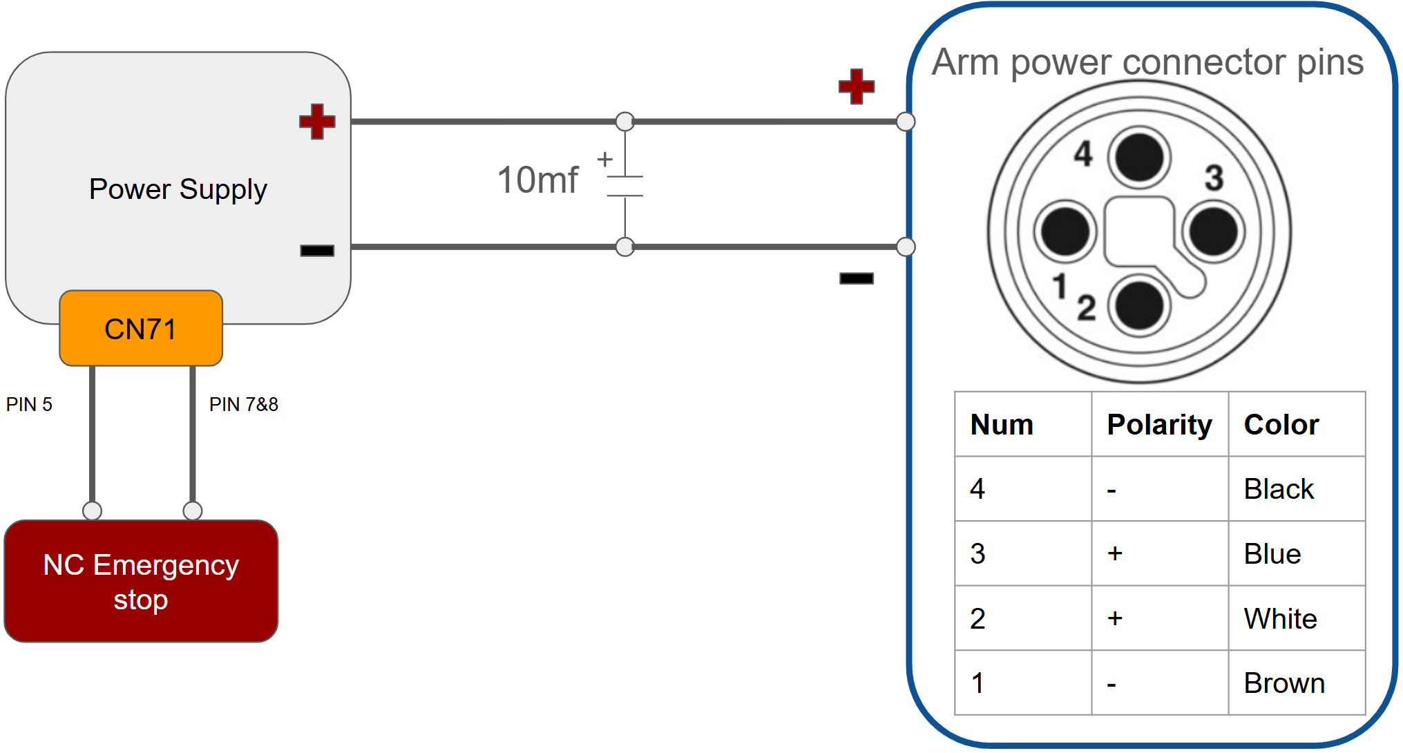
Fig. 9 Illustration of the recommended power wiring configuration
Key Wiring Points:
Capacitor Connection: Connect the 10 mF capacitor in parallel to the power distributor output to handle regenerative braking and absorb voltage spikes, as shown in the diagram above.
Emergency Stop: Connect a Normally Closed emergency stop button to the Remote ON-OFF pins (PIN 5 and PIN 7-8) of the power distributor. Refer to the Mean Well HEP-1000 datasheet for detailed pin specifications.
Optional Discharge Resistor: An additional resistor may be connected in parallel with the capacitor to facilitate faster discharge after system shutdown. While this has not been extensively tested, it may be beneficial if rapid capacitor discharge is required for your application.
Safety Guidelines
Emergency Stop:
Always ensure the emergency stop button is easily accessible during operation.
Test the emergency stop functionality before every session.
Safe Work Area:
Maintain a clear workspace around the robot.
Avoid placing objects within the robot’s operational range.
Start-Up Precautions:
Be aware that the robot may move slightly during activation.
Never stand within the robot’s range during start-up or shutdown.
Routine Inspections:
Check for loose screws, damaged cables, or other potential hazards before each use.
Inspect the mounting base periodically to ensure stability.
Warning Signs:
Place visible warning signs near the robot to alert operators and bystanders of potential risks.
Warning
Failure to follow these guidelines may result in equipment damage or personal injury.